ELECTROMAGNETIC PULSE (EMP) AND TEMPEST PROTECTION FOR FACILITIES
Table of Contents: http://jya.com/emp.htm
------------------------------------------------------------------------------
CHAPTER 3
EMP HARDENING CONCEPTS FOR FACILITIES
3-1. Outline. This chapter is organized as follows:
3-1. Outline
3-2. Discussion of general concepts
a. System functions
b. Survival confidence
(1) Levels of confidence
(2) Inherent uncertainties
c. Critical equipment sensitivities
(1) Design margin
(2) Coupled energy
d. Potential HEMP coupling paths
e. Design verifiability
(1) Hardness validation
(2) Retrofit designs
(3) Designing to facilitate testing
(4) Approaches to validation
f. Physical environment
g. Other factors
3-3. Description of HEMP hardening concepts
a. Shielding
(1) Global shielding
(2) Tailored shielding
(3) Zonal or topological shielding
(4) System configuration
(5) Cable shielding
(6) Grounding
b. Hardening allocation concept
c. Shield penetration protection concepts
(1) Large access doors
(2) Personnel entrances
(3) Electrical penetrations
(4) Transient suppression devices and filters
(5) Electromagnetic isolation
(6) Dielectric isolation
(7) Isolation switching
3-4. Cited references
3-5. Uncited references
------------------------------------------------------------------------------
3-2. Discussion of general concepts. The HEMP environment is defined by DOD-
STD-2169. This definition includes the classification and specific
information on field strengths, pulse characteristics, spectral content, angle
of arrival, range of relative burst locations, and weapon yield.
a. System functions. Associated with the electronic and electrical
systems and subsystems to be protected are support functions such as
utilities, personnel housing, office space, document storage, food facilities,
and others. Many aspects of a facility are not sensitive to HEMP energy or
are robust enough that HEMP protection is not required. Some sensitive system
elements may not be critical to the facility mission. The definition of
mission-essential functions that must remain in operation will have major
impact on the choice of hardening concepts.
b. Survival confidence. The issue of defining "survivability
requirements" must be specifically addressed and resolved in the concept
definition phase of each particular HEMP hardening effort. The system user
should define the required survival confidence level, at least qualitatively,
since this factor will determine how conservative the design will be. If
required confidence levels are high, greater safety margins in protection
levels will be required, producing a need for a high-quality overall shield
and adequate validation testing.
(1) Levels of confidence. Survivability confidence may require that a
facility--
(a) Experience no HEMP-induced stress greater than the stresses
occurring in the normal operating environment.
(b) Experience neither permanent nor operational upset as a result
of the HEMP.
(2) Inherent uncertainties. Another survivability issue concerns the
inherent and analytical uncertainties in quantifying the stress level causing
malfunction or the stress level experienced by the equipment.
c. Critical equipment sensitivities. The main factors in determining
required protection levels are--
(1) Design margin. The design margin required, which is related to the
difference between critical equipment sensitivities and coupled transients.
(2) Coupled energy. The energy level coupled from connected subsystems
or components.
d. Potential HEMP coupling paths. Most electronic/ electrical systems to
be HEMP-hardened and their housing facilities will have to interface with
external elements such as antennas, utilities, communications lines, and other
facilities. The complexity of interfacing and possible coupling paths for
HEMP energy will greatly affect the choice of topological approaches to HEMP
hardening.
e. Design verifiability.
(1) Hardness validation. A key issue in HEMP hardening philosophy and
associated design concepts is that of hardness validation and required confi-
dence levels for final acceptance. (Required confidence levels are usually
specified only qualitatively.) Generally, the more critical the facility is
to national military security, the more politically and publicly visible it
will be; for these facilities, higher confidence levels will be required. In
all cases, design concepts may not be chosen if they cannot be validated with
acceptable confidence levels. For example, a design concept for a large
underground facility that depends on a degree of protection from the overbur-
den and has numerous conducting penetrations through the overburden may have
hardness uncertainties. Examples include questions about the homogeneity of
the overburden and difficulties in protecting penetrations when no highly
conductive shield is present. If the facility is too large to be practically
subjected to a threat level test by an EMP simulator and no other proven vali-
dation tests exist, the uncertainties will prevail and hardness confidence
will be low.
(2) Retrofit designs. In retrofit designs, another consideration-in
concept selection may be the ability to validate hardness without disrupting
the operation of critical systems. Concepts should be chosen to allow
nondisruptive validation and acceptance testing.
(3) Designing to facilitate testing. Good design validation requires a
choice of design concepts that facilitate testing. HEMP hardening management
must include adequate funding and scheduling for this effort. The difficulty
and cost of validation will increase with--
(a) System complexity.
(b) Topology layer and zone numbers.
(c) The number of required penetrations.
(d) The protective design philosophy.
(4) Approaches to validation. In considering the validation problem
for concept selection, it is helpful to review the many approaches to valida-
tion, including laboratory testing, full-scale HEMP threat level field
testing, partial scale threat-level field testing, current injection testing,
scale model testing, physical modeling testing, computer modeling evaluations,
analyses, and radio frequency CW shielding tests.
f. Physical environment. Various aspects of the facility physical
environment can greatly affect concept selection, mainly in the degree to
which corrosion can accelerate aging and degradation of protection.
g. Other factors. Other factors to be considered in concept selection
are--
(1) Complexity of required interactions with facilities.
(2) Design and construction costs.
(3) Constructibility.
(4) Maintenance costs.
(5) Reliability requirements.
(6) Flexibility for expansion or system changes.
(7) New construction versus retrofit.
(8) Supportability.
3-3. Description of HEMP hardening concepts.
a. Shielding. For HEMP-hardened facilities, some kind of EM shielding is
essential. Shielding theory is discussed in detail in chapter 5 and is
treated thoroughly in the literature. Shielding involves the use of a barrier
or series of barriers to reduce the magnitude of the EM energy incident upon
the electronic or electrical system to be protected. Shielding philosophy can
be developed around different approaches as discussed in paragraphs (1)
through (6) below and shown in figure 3-1.
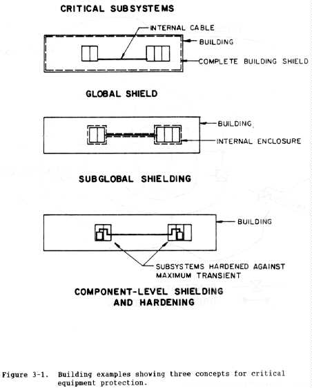 (1) Global shielding. Global shielding (or hardening) is a protection
concept that uses an overall shield to encompass the entire facility. In this
approach, all conducting penetrations and all apertures are protected at the
shield. The intent is to keep all HEMP fields and HEMP-induced transients
outside the protected volume. The global shield could be placed on the entire
outer walls, ceiling, and floor (surface) of the facility, or it could be
reduced to a smaller volume that contains all sensitive equipment to be
protected. The most common shield material for global shielding of ground-
based facilities is sheet steel with welded seams, although other designs can
provide adequate global HEMP shielding.
(a) Global shielding may be desirable if there is a requirement to
be able to modify, reorganize, add to, or move the sensitive equipment without
changing the shield or protective features.
(b) A remote, yet possible, disadvantage of global shielding that
must be considered is that a single protective component or device failure may
jeopardize the entire facility.
(2) Tailored shielding. Tailored shielding is a protection concept in
which shielding is designed and constructed according to specific protection
requirements for the equipment involved. After defining the system to be
protected, its possible operating configurations, the expected HEMP
environment, coupling paths, equipment sensitivities, and subsystem/system
criticalities, the required protection levels for various subsystems or groups
of subsystems can be defined. Tradeoff studies may be performed for comparing
various shielding arrangements to verify that they meet safety margins in
protection, cost-effectiveness, maintainability, survivability, flexibility,
and other requirements. The objective is to optimize protection for the
specific mission-critical system. Tailored shielding options may include
global shielding, zonal shielding (discussed under (3) below), shielding of
cabinets or components, or combinations thereof. In a typical tailored
protection design, discrete protection will be provided to eliminate specific,
localized deficiencies.
(3) Zonal or topological shielding. Zonal or topological shielding
(ref 3-1) is a concept in which a facility is divided into zones, with
shielding barriers located topologically in a shield within a shield
configuration. Figure 3-2 shows a generic topological shielding system. The
outer zone is designated zone 0; zone 1 is inside shield 1 but outside shield
2. Zones and shields are assigned increasingly larger numbers as they
progress toward the more deeply nested areas.
(1) Global shielding. Global shielding (or hardening) is a protection
concept that uses an overall shield to encompass the entire facility. In this
approach, all conducting penetrations and all apertures are protected at the
shield. The intent is to keep all HEMP fields and HEMP-induced transients
outside the protected volume. The global shield could be placed on the entire
outer walls, ceiling, and floor (surface) of the facility, or it could be
reduced to a smaller volume that contains all sensitive equipment to be
protected. The most common shield material for global shielding of ground-
based facilities is sheet steel with welded seams, although other designs can
provide adequate global HEMP shielding.
(a) Global shielding may be desirable if there is a requirement to
be able to modify, reorganize, add to, or move the sensitive equipment without
changing the shield or protective features.
(b) A remote, yet possible, disadvantage of global shielding that
must be considered is that a single protective component or device failure may
jeopardize the entire facility.
(2) Tailored shielding. Tailored shielding is a protection concept in
which shielding is designed and constructed according to specific protection
requirements for the equipment involved. After defining the system to be
protected, its possible operating configurations, the expected HEMP
environment, coupling paths, equipment sensitivities, and subsystem/system
criticalities, the required protection levels for various subsystems or groups
of subsystems can be defined. Tradeoff studies may be performed for comparing
various shielding arrangements to verify that they meet safety margins in
protection, cost-effectiveness, maintainability, survivability, flexibility,
and other requirements. The objective is to optimize protection for the
specific mission-critical system. Tailored shielding options may include
global shielding, zonal shielding (discussed under (3) below), shielding of
cabinets or components, or combinations thereof. In a typical tailored
protection design, discrete protection will be provided to eliminate specific,
localized deficiencies.
(3) Zonal or topological shielding. Zonal or topological shielding
(ref 3-1) is a concept in which a facility is divided into zones, with
shielding barriers located topologically in a shield within a shield
configuration. Figure 3-2 shows a generic topological shielding system. The
outer zone is designated zone 0; zone 1 is inside shield 1 but outside shield
2. Zones and shields are assigned increasingly larger numbers as they
progress toward the more deeply nested areas.
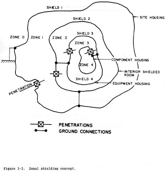 (a) Note that figure 3-2 is a simple schematic to represent the
zoning concept; although not depicted, each zone could contain more sets of
subzones. For example, shield 3 could contain 2 or more zones designated as
zone 4. Further, figure 3-2 shows possible shield types including a site
housing shield and an interior shielded room, with equipment and component
housings making up the shields of the next topological orders.
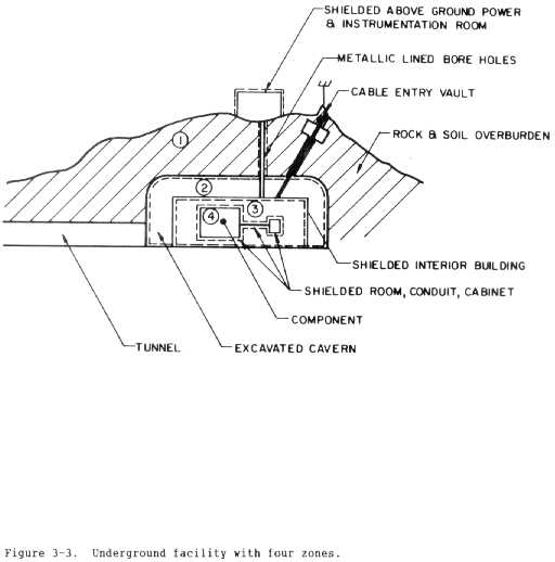
(b) The zonal concept shown in figure 3-3 is a specific example of
an underground facility that uses topologically zoned protection. The rock
and soil overburden above the facility serves as shield 1. Zone 1 is the
volume between the underground building and the excavated outline of overhead
rock. In some cases, a shield of this type provides adequate protection for
robust electrical or electronic equipment. Shield 2 is composed of a sheet
metal building that may provide only a limited level of shielding. Inside
this building (zone 2), some systems would be adequately protected. The
above-ground building and connecting conduit represent an extension of zone 2.
Shield 3 is then the interior shielded room which provides further protection
within zone 3. where sensitive, electronic equipment may be operated.
(a) Note that figure 3-2 is a simple schematic to represent the
zoning concept; although not depicted, each zone could contain more sets of
subzones. For example, shield 3 could contain 2 or more zones designated as
zone 4. Further, figure 3-2 shows possible shield types including a site
housing shield and an interior shielded room, with equipment and component
housings making up the shields of the next topological orders.
(b) The zonal concept shown in figure 3-3 is a specific example of
an underground facility that uses topologically zoned protection. The rock
and soil overburden above the facility serves as shield 1. Zone 1 is the
volume between the underground building and the excavated outline of overhead
rock. In some cases, a shield of this type provides adequate protection for
robust electrical or electronic equipment. Shield 2 is composed of a sheet
metal building that may provide only a limited level of shielding. Inside
this building (zone 2), some systems would be adequately protected. The
above-ground building and connecting conduit represent an extension of zone 2.
Shield 3 is then the interior shielded room which provides further protection
within zone 3. where sensitive, electronic equipment may be operated.
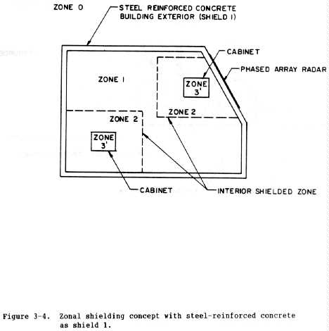
 (c) Figure 3-4 shows another specific example of a zonal or
topographically shielded facility for which steel-reinforced concrete
comprises shield 1. This type of shield usually does not provide adequate
protection and thus the additional shields are necessary.
(c) Figure 3-4 shows another specific example of a zonal or
topographically shielded facility for which steel-reinforced concrete
comprises shield 1. This type of shield usually does not provide adequate
protection and thus the additional shields are necessary.
 (4) System configuration. The term "system configuration" identifies
which way the cables, wires, equipment, and subsystems are laid out in
relationship to each other, as well as the relationship of these items to the
topological boundaries. In some instances, the cables, connectors, and
equipment casings are actually part of the topological protection. Although
"system configuration" as defined does not directly attenuate the environment,
it is an important element in the topological protection concept. The system
configuration influences protection design requirements since some
configurations are easier to protect than others ~e.g., collocation of all
mission-critical equipment). Thus, the system configuration should be
coordinated with the protection design and the protection topology will be
optimal for a specific configuration. During the facility life cycle, the
protection design may be required to accommodate some changes in
configuration. To ensure that the configuration's design modifications do not
compromise or defeat the protection, careful configuration management is
necessary. The topology should be designed to tolerate configuration changes
that are totally within a boundary. The boundary can never be violated (for
example, opened)--only extended. All modifications must be subjected to
review by EMP experts to ensure continual compliance with the HEMP hardening
requirements.
(5) Cable shielding. Conductive or metallic cable shielding or conduit
is used in the zonal/topological protection concept to extend the boundary
formed by equipment enclosures and thus provide a way to interconnect elements
while maintaining boundary continuity. Cable shielding is also used to
protect a wire or wires as they travel from one boundary to another. This
would be the case with a shielded RF signal traveling from its entrance into a
building to the RF receiver. From a HEMP standpoint, the shielding attenuates
coupling of radiated energy within the first boundary as the signal travels to
the receiver. Of course the shield is somewhat reciprocal in that it also
prevents signals from radiating out of the cable. The main feature of cable
shielding stressed here is continuity of the boundary provided by the cable
shield/connector combination which may require special joints.
(a) Another way to maintain this continuity and provide cable
shielding is by using steel conduit to house all wires and cables. The steel
conduit will provide substantially higher shielding levels than the cable
shields. Chapter 5 presents conduit system design in detail.
(b) Both cable shields and conduit connected to a shielded zone must
have equal or greater shielding effectiveness than the shield.
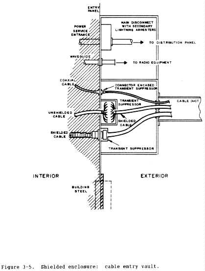
(c) Figure 3-5 shows a cable entry vault used to protect cable
penetrations through a shield. Entry vaults are discussed under shield
penetrations in paragraph c below.
(4) System configuration. The term "system configuration" identifies
which way the cables, wires, equipment, and subsystems are laid out in
relationship to each other, as well as the relationship of these items to the
topological boundaries. In some instances, the cables, connectors, and
equipment casings are actually part of the topological protection. Although
"system configuration" as defined does not directly attenuate the environment,
it is an important element in the topological protection concept. The system
configuration influences protection design requirements since some
configurations are easier to protect than others ~e.g., collocation of all
mission-critical equipment). Thus, the system configuration should be
coordinated with the protection design and the protection topology will be
optimal for a specific configuration. During the facility life cycle, the
protection design may be required to accommodate some changes in
configuration. To ensure that the configuration's design modifications do not
compromise or defeat the protection, careful configuration management is
necessary. The topology should be designed to tolerate configuration changes
that are totally within a boundary. The boundary can never be violated (for
example, opened)--only extended. All modifications must be subjected to
review by EMP experts to ensure continual compliance with the HEMP hardening
requirements.
(5) Cable shielding. Conductive or metallic cable shielding or conduit
is used in the zonal/topological protection concept to extend the boundary
formed by equipment enclosures and thus provide a way to interconnect elements
while maintaining boundary continuity. Cable shielding is also used to
protect a wire or wires as they travel from one boundary to another. This
would be the case with a shielded RF signal traveling from its entrance into a
building to the RF receiver. From a HEMP standpoint, the shielding attenuates
coupling of radiated energy within the first boundary as the signal travels to
the receiver. Of course the shield is somewhat reciprocal in that it also
prevents signals from radiating out of the cable. The main feature of cable
shielding stressed here is continuity of the boundary provided by the cable
shield/connector combination which may require special joints.
(a) Another way to maintain this continuity and provide cable
shielding is by using steel conduit to house all wires and cables. The steel
conduit will provide substantially higher shielding levels than the cable
shields. Chapter 5 presents conduit system design in detail.
(b) Both cable shields and conduit connected to a shielded zone must
have equal or greater shielding effectiveness than the shield.
(c) Figure 3-5 shows a cable entry vault used to protect cable
penetrations through a shield. Entry vaults are discussed under shield
penetrations in paragraph c below.
 (6) Grounding. Some form of grounding is required in any electrical or
electronic system for protecting personnel from electrical shock, controlling
interference, proper shunting of transient currents around sensitive
electronics, and other reasons. (Grounding does not directly provide
protection against EMP, but must be done properly to prevent creation of more
serious EMP vulnerabilities.) Ideally, grounding would keep all system
components at a common potential. In practice, because of possible inductive
loops, capacitive coupling, line and bonding impedances, antenna ringing
effects, and other phenomena, large potentials may exist on grounding
circuits. The choice of grounding concept is therefore important in the HEMP
protection philosophy.
b. Hardening allocation concept. The shielding concepts in this chapter
introduce the concept of hardening allocation in which the overall protection
philosophy specifies degrees of hardening for each zone. The practicality of
this concept usually depends on the complexity of the system to be protected.
If it is determined that an overall SE of 80 decibels is required for the most
sensitive components, but the remaining elements require only 60 decibels,
then zones with different SE may be established. The cost-effectiveness of a
zonal design with a hardening allocation for each barrier must be studied
carefully on a facility/ system specific basis to determine the practicality
of this approach.
c. Shield penetration protection concepts. All shielded zones will
require penetrations to allow entry of equipment, personnel, electric power,
communications, and control signals, ventilation, water, fuel, and various
fluids. Without Protection, these penetrations compromise the shield.
(l) Large access doors. Large access doors are often necessary to
provide an entry for equipment, supplies, or vehicles into EMP hardened
facilities. In facilities that require blast overpressure protection, large
blast doors are used. These doors generally use one or more thick steel
plates to provide protection. The door's inherent shielding ability is thus
high, but its large size presents a difficult gasketing problem. If blast
protection is not required, it is still necessary to design the door with a
high degree of structural strength. This step is to ensure that the door can
provide the necessary gasket compression force and that proper mechanical
alignment of closure contact surfaces is maintained.
(2) Personnel entrances. Two concepts are commonly used for personnel
entrances: conventional EMP/RFI shielded doors and personnel tunnels that act
as waveguides below cutoff. The shielded doors generally use metal
fingerstock or EMI/RFI gaskets to provide an electromagnetic seal around the
door jamb periphery. Currently available gasket and fingerstock doors require
regularly scheduled maintenance and/or replacement to maintain required
shielding levels. The gaskets are relatively easily damaged and also require
replacement. Air-expandable doors may also be used, although they typically
have more maintenance problems. These doors generally use a movable
subassembly of two shielding plates on a framework that is moved on rollers in
and out of a steel-framed opening. When closed, air expansion tubes cause the
two shielding plates to make uniform surface contact with the frame inner
surfaces.
(a) Fingerstock doors can provide over 80 decibels of shielding to
magnetic fields from 100 kilohertz through 30 megahertz and greater SE to
plane waves and electric fields. Air-expandable doors can provide greater
than 120 decibels of magnetic field SE from 10 kilohertz to 10 gigahertz.
(b) Air-expandable doors require an air source and air controls with
back-up in safety controls. They also require very strong steel frames and,
as a result, are more expensive than gasketed doors. They are also more
difficult and costly to maintain. The air-expandable door would thus be used
only when a large safety margin of HEMP shielding is needed or when equipment
to be protected is extremely sensitive to HEMP or other EM interference.
(c) The waveguide entry tunnel acts as a WBC that will typically
have a cutoff frequency* in the 60-megahertz region. Thus, the higher
frequencies in the HEMP spectrum will penetrate it. Doors are therefore
required to prevent the higher frequency signals from penetrating. Since only
high frequencies can propagate through, doors have good attenuation in this
range and can easily provide the required attenuation. Maintenance require-
ments are not as stringent as for doors that must block the entire frequency
spectrum; thus, the waveguide entry tunnel for personnel access is attractive
from a life-cycle cost standpoint. When the facility has a TEMPEST
requirement as well as EMP shielding requirements, the tunnel is usually
designed with interlocking doors, i.e., a door at each end and interlocked so
that only one door can be opened at once, thus preventing any leakage of
classified information during the entry of personnel. The waveguide entry
tunnel also is highly useful in underground or buried facilities because the
overburden attenuates the high frequencies, thus acting to complement the
tunnel attentuation.
________________________
*Cutoff frequency is determined by the relationship Fo = 5900 MHz/W, where W is
the greatest cross sectional dimension in inches. Below cutoff, the waveguide
attenuation is a function of the waveguide length. In practice, the length-to-
width ratio should be 5.
(3) Electrical penetrations. A common feature for electrical
penetrations in a global protection approach is a cable entry vault to prevent
large currents on external conductors from being conducted into the facility.
Ideally, all penetrations should enter a single vault. In some cases,
however, it may be necessary to separate the vault into two compartments or to
use two vaults for penetrations by different types of lines: power, signal
and control, and antenna. The vault must be connected directly to the
external facility ground system. (See chapter 5 for details.) The cable
entry vault serves three purposes: to insure that penetrating conductors do
not cause conducted HEMP energy to enter the protected topology; to contain
and divert penetrator-conducted HEMP energy to the boundary exterior; and to
contain or divert radiant EM energy resulting from the activation of transient
suppression devices subjected to a conducted pulse. Conductive penetrations,
such as a conduit, waveguide, or shielded cable, must have a circumferential
weld or other means of providing good electrical connection at the
intersection with the entry vault.
(4) Transient suppression devices and filters. Transient suppression
devices fill a critical gap in the concept of topological protection. The
necessity of supplying power to a facility and of communicating over cables or
antennas are two major factors contributing to their use. Power lines
entering a facility are typically connected to an unshielded power grid so
that large, conducted currents must be bled off to prevent their entry into a
facility.* These currents are diverted to the exterior boundary of the
topology. This boundary can be an overall external shield or an enclosed en-
trance vault. Antennas, such as for high-frequency (HF) communications, are
designed to gather EM signals (at wavelengths in the EMP frequency spectrum)
and to apply these signals to the center conductor of a shielded cable. The
EMP transients associated with an HF antenna can be, by far, the largest
single signal entering a facility. Transient suppressors often are used in
conjunction with filters. Filters are frequency-selective whereas surge
suppressors are amplitude-selective. Filters often are used to attenuate
transients associated with the nonlinear operation of surge arresters. They
also are used for selectively passing (or stopping) frequency bands as in the
case of antenna cable penetrations. Transient suppressors are an integral
part of the EM topology, demanding specific installation techniques as will be
seen later. A spark gap is a surge suppressor that provides a conducting path
to ground when the voltage across the device exceeds the gap breakdown level.
Spark gaps with a high current capacity do not operate quickly enough to block
all HEMP energy transients entering the vault. For this reason, it may be
necessary to use other protection devices in conjunction with the spark gap.
________________________
*Within a facility, inside shield 1, power lines are often
routed through steel conduits to provide shielding.
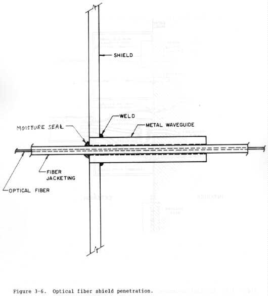
(5) Electromagnetic isolation. The electromagnetic isolation concept
involves the use of elements either immune to interaction with EM radiation or
that provide a current path interruption. Optical fibers are examples of
elements immune to EM radiation that can be used to reduce the number of
conductive penetrations. For practical purposes, optical fibers can be used
for long communications links without signal interference from HEMP. Further,
they can be used to enter shielded zones through waveguide below cutoff
penetrations without compromising the EM shielding effectiveness, as figure 3-
6 shows. Where possible, optical fibers are recommended for--
(a) Voice and data communications lines.
(b) Energy monitoring and control systems (EMCS).
(c) Intrusion detection systems.
(d) Other security systems.
(e) Control systems.
(f) Any other use where possible and practical.
(6) Grounding. Some form of grounding is required in any electrical or
electronic system for protecting personnel from electrical shock, controlling
interference, proper shunting of transient currents around sensitive
electronics, and other reasons. (Grounding does not directly provide
protection against EMP, but must be done properly to prevent creation of more
serious EMP vulnerabilities.) Ideally, grounding would keep all system
components at a common potential. In practice, because of possible inductive
loops, capacitive coupling, line and bonding impedances, antenna ringing
effects, and other phenomena, large potentials may exist on grounding
circuits. The choice of grounding concept is therefore important in the HEMP
protection philosophy.
b. Hardening allocation concept. The shielding concepts in this chapter
introduce the concept of hardening allocation in which the overall protection
philosophy specifies degrees of hardening for each zone. The practicality of
this concept usually depends on the complexity of the system to be protected.
If it is determined that an overall SE of 80 decibels is required for the most
sensitive components, but the remaining elements require only 60 decibels,
then zones with different SE may be established. The cost-effectiveness of a
zonal design with a hardening allocation for each barrier must be studied
carefully on a facility/ system specific basis to determine the practicality
of this approach.
c. Shield penetration protection concepts. All shielded zones will
require penetrations to allow entry of equipment, personnel, electric power,
communications, and control signals, ventilation, water, fuel, and various
fluids. Without Protection, these penetrations compromise the shield.
(l) Large access doors. Large access doors are often necessary to
provide an entry for equipment, supplies, or vehicles into EMP hardened
facilities. In facilities that require blast overpressure protection, large
blast doors are used. These doors generally use one or more thick steel
plates to provide protection. The door's inherent shielding ability is thus
high, but its large size presents a difficult gasketing problem. If blast
protection is not required, it is still necessary to design the door with a
high degree of structural strength. This step is to ensure that the door can
provide the necessary gasket compression force and that proper mechanical
alignment of closure contact surfaces is maintained.
(2) Personnel entrances. Two concepts are commonly used for personnel
entrances: conventional EMP/RFI shielded doors and personnel tunnels that act
as waveguides below cutoff. The shielded doors generally use metal
fingerstock or EMI/RFI gaskets to provide an electromagnetic seal around the
door jamb periphery. Currently available gasket and fingerstock doors require
regularly scheduled maintenance and/or replacement to maintain required
shielding levels. The gaskets are relatively easily damaged and also require
replacement. Air-expandable doors may also be used, although they typically
have more maintenance problems. These doors generally use a movable
subassembly of two shielding plates on a framework that is moved on rollers in
and out of a steel-framed opening. When closed, air expansion tubes cause the
two shielding plates to make uniform surface contact with the frame inner
surfaces.
(a) Fingerstock doors can provide over 80 decibels of shielding to
magnetic fields from 100 kilohertz through 30 megahertz and greater SE to
plane waves and electric fields. Air-expandable doors can provide greater
than 120 decibels of magnetic field SE from 10 kilohertz to 10 gigahertz.
(b) Air-expandable doors require an air source and air controls with
back-up in safety controls. They also require very strong steel frames and,
as a result, are more expensive than gasketed doors. They are also more
difficult and costly to maintain. The air-expandable door would thus be used
only when a large safety margin of HEMP shielding is needed or when equipment
to be protected is extremely sensitive to HEMP or other EM interference.
(c) The waveguide entry tunnel acts as a WBC that will typically
have a cutoff frequency* in the 60-megahertz region. Thus, the higher
frequencies in the HEMP spectrum will penetrate it. Doors are therefore
required to prevent the higher frequency signals from penetrating. Since only
high frequencies can propagate through, doors have good attenuation in this
range and can easily provide the required attenuation. Maintenance require-
ments are not as stringent as for doors that must block the entire frequency
spectrum; thus, the waveguide entry tunnel for personnel access is attractive
from a life-cycle cost standpoint. When the facility has a TEMPEST
requirement as well as EMP shielding requirements, the tunnel is usually
designed with interlocking doors, i.e., a door at each end and interlocked so
that only one door can be opened at once, thus preventing any leakage of
classified information during the entry of personnel. The waveguide entry
tunnel also is highly useful in underground or buried facilities because the
overburden attenuates the high frequencies, thus acting to complement the
tunnel attentuation.
________________________
*Cutoff frequency is determined by the relationship Fo = 5900 MHz/W, where W is
the greatest cross sectional dimension in inches. Below cutoff, the waveguide
attenuation is a function of the waveguide length. In practice, the length-to-
width ratio should be 5.
(3) Electrical penetrations. A common feature for electrical
penetrations in a global protection approach is a cable entry vault to prevent
large currents on external conductors from being conducted into the facility.
Ideally, all penetrations should enter a single vault. In some cases,
however, it may be necessary to separate the vault into two compartments or to
use two vaults for penetrations by different types of lines: power, signal
and control, and antenna. The vault must be connected directly to the
external facility ground system. (See chapter 5 for details.) The cable
entry vault serves three purposes: to insure that penetrating conductors do
not cause conducted HEMP energy to enter the protected topology; to contain
and divert penetrator-conducted HEMP energy to the boundary exterior; and to
contain or divert radiant EM energy resulting from the activation of transient
suppression devices subjected to a conducted pulse. Conductive penetrations,
such as a conduit, waveguide, or shielded cable, must have a circumferential
weld or other means of providing good electrical connection at the
intersection with the entry vault.
(4) Transient suppression devices and filters. Transient suppression
devices fill a critical gap in the concept of topological protection. The
necessity of supplying power to a facility and of communicating over cables or
antennas are two major factors contributing to their use. Power lines
entering a facility are typically connected to an unshielded power grid so
that large, conducted currents must be bled off to prevent their entry into a
facility.* These currents are diverted to the exterior boundary of the
topology. This boundary can be an overall external shield or an enclosed en-
trance vault. Antennas, such as for high-frequency (HF) communications, are
designed to gather EM signals (at wavelengths in the EMP frequency spectrum)
and to apply these signals to the center conductor of a shielded cable. The
EMP transients associated with an HF antenna can be, by far, the largest
single signal entering a facility. Transient suppressors often are used in
conjunction with filters. Filters are frequency-selective whereas surge
suppressors are amplitude-selective. Filters often are used to attenuate
transients associated with the nonlinear operation of surge arresters. They
also are used for selectively passing (or stopping) frequency bands as in the
case of antenna cable penetrations. Transient suppressors are an integral
part of the EM topology, demanding specific installation techniques as will be
seen later. A spark gap is a surge suppressor that provides a conducting path
to ground when the voltage across the device exceeds the gap breakdown level.
Spark gaps with a high current capacity do not operate quickly enough to block
all HEMP energy transients entering the vault. For this reason, it may be
necessary to use other protection devices in conjunction with the spark gap.
________________________
*Within a facility, inside shield 1, power lines are often
routed through steel conduits to provide shielding.
(5) Electromagnetic isolation. The electromagnetic isolation concept
involves the use of elements either immune to interaction with EM radiation or
that provide a current path interruption. Optical fibers are examples of
elements immune to EM radiation that can be used to reduce the number of
conductive penetrations. For practical purposes, optical fibers can be used
for long communications links without signal interference from HEMP. Further,
they can be used to enter shielded zones through waveguide below cutoff
penetrations without compromising the EM shielding effectiveness, as figure 3-
6 shows. Where possible, optical fibers are recommended for--
(a) Voice and data communications lines.
(b) Energy monitoring and control systems (EMCS).
(c) Intrusion detection systems.
(d) Other security systems.
(e) Control systems.
(f) Any other use where possible and practical.
 (6) Dielectric isolation. Other isolation techniques include using
dielectric isolators for shield penetration when external metallic EM energy
collectors are involved. Examples are control rods* or cables (normally
metallic), piping systems for fluids, and metallic duct systems for air.
Dielectric sections are installed at or near the shield to prevent the energy
induced on the external metallic part from being conducted through the shield.
Dielectric control rods can enter through a shield in the same way as optical
fibers, that is, through a waveguide-below-cutoff section. Dielectric isola-
tion concepts for metallic piping systems and air ducts are discussed in
chapter 5.
_________________________
* Rods that must be mechanically rotated or pulled to control switches, valves,
and other components.
(7) Isolation switching. Although not recommended now, isolation
switching has been provided at facilities so they can use commercial electric
power during routine operation, but can switch to internal generators or power
systems in the event of an emergency such as nuclear attack. Since the
commercial power wiring is a source of significant HEMP energy injection
through a shield, switching to internally generated power is an obvious
advantage when advance warning of impending nuclear attack is received and
throughout the entire nuclear attack cycle. This concept applies to
communications lines and control lines as well as power lines. Switching used
in past facility designs has been called "alert attack" switching. Such
switching must provide adequate switch contact separation to prevent arcing,
and must be designed to reduce coupling interactions between wiring and switch
contacts to acceptable levels. It should be noted that advance notice of a
HEMP attack is not always provided.
3-4. Cited reference.
3-1. Vance, E. F., Shielding and Grounding Topology for Interference
Control, Interaction Note 306 (Air Force Weapons Laboratory
[AFWL], APril 1977).
3-5. Uncited references.
Bailey, D. T., et al., EMP Hardening Guidelines: System Life Cycle
Cost Design Considerations, AWFL-TR-79-161 (AWFL, May 1980).
BDM Corporation, Defense Nuclear Agency (DNA) EMP Course (Draft),
BDM/W-82-305-TR (DNA, April 1983).
Mindel, I. N., DNA EMP Awareness Course Notes, Third Edition, DNA
2772T (October 1977).
------------------------------------------------------------------------------
[End Chapter 3]
(6) Dielectric isolation. Other isolation techniques include using
dielectric isolators for shield penetration when external metallic EM energy
collectors are involved. Examples are control rods* or cables (normally
metallic), piping systems for fluids, and metallic duct systems for air.
Dielectric sections are installed at or near the shield to prevent the energy
induced on the external metallic part from being conducted through the shield.
Dielectric control rods can enter through a shield in the same way as optical
fibers, that is, through a waveguide-below-cutoff section. Dielectric isola-
tion concepts for metallic piping systems and air ducts are discussed in
chapter 5.
_________________________
* Rods that must be mechanically rotated or pulled to control switches, valves,
and other components.
(7) Isolation switching. Although not recommended now, isolation
switching has been provided at facilities so they can use commercial electric
power during routine operation, but can switch to internal generators or power
systems in the event of an emergency such as nuclear attack. Since the
commercial power wiring is a source of significant HEMP energy injection
through a shield, switching to internally generated power is an obvious
advantage when advance warning of impending nuclear attack is received and
throughout the entire nuclear attack cycle. This concept applies to
communications lines and control lines as well as power lines. Switching used
in past facility designs has been called "alert attack" switching. Such
switching must provide adequate switch contact separation to prevent arcing,
and must be designed to reduce coupling interactions between wiring and switch
contacts to acceptable levels. It should be noted that advance notice of a
HEMP attack is not always provided.
3-4. Cited reference.
3-1. Vance, E. F., Shielding and Grounding Topology for Interference
Control, Interaction Note 306 (Air Force Weapons Laboratory
[AFWL], APril 1977).
3-5. Uncited references.
Bailey, D. T., et al., EMP Hardening Guidelines: System Life Cycle
Cost Design Considerations, AWFL-TR-79-161 (AWFL, May 1980).
BDM Corporation, Defense Nuclear Agency (DNA) EMP Course (Draft),
BDM/W-82-305-TR (DNA, April 1983).
Mindel, I. N., DNA EMP Awareness Course Notes, Third Edition, DNA
2772T (October 1977).
------------------------------------------------------------------------------
[End Chapter 3]